Visualisations
The AusGeol virtual library provides a variety of geological visualisations.
3D Photogrammetric Models (VisType : 3D)
3D models are generated from digital photographs using 'structure from motion' algorithms. All AusGeol 3D models have been created using Agisoft Photoscan software (http://www.agisoft.com/).

The process begins with digital photography undertaken with any digital imaging device (even mobile phones). It is not necessary to know either the characteristics of the camera or the position and orientation for each image, these parameters are determined automatically during processing. The quality of the final visualisation is determined by: image quality, the number of images, the relative positions and orientations of the images, and the geometric complexity of the outcrop.
Digital photography guuidelines for photogrammetry are provided in a PDF file: Photography Guidelines
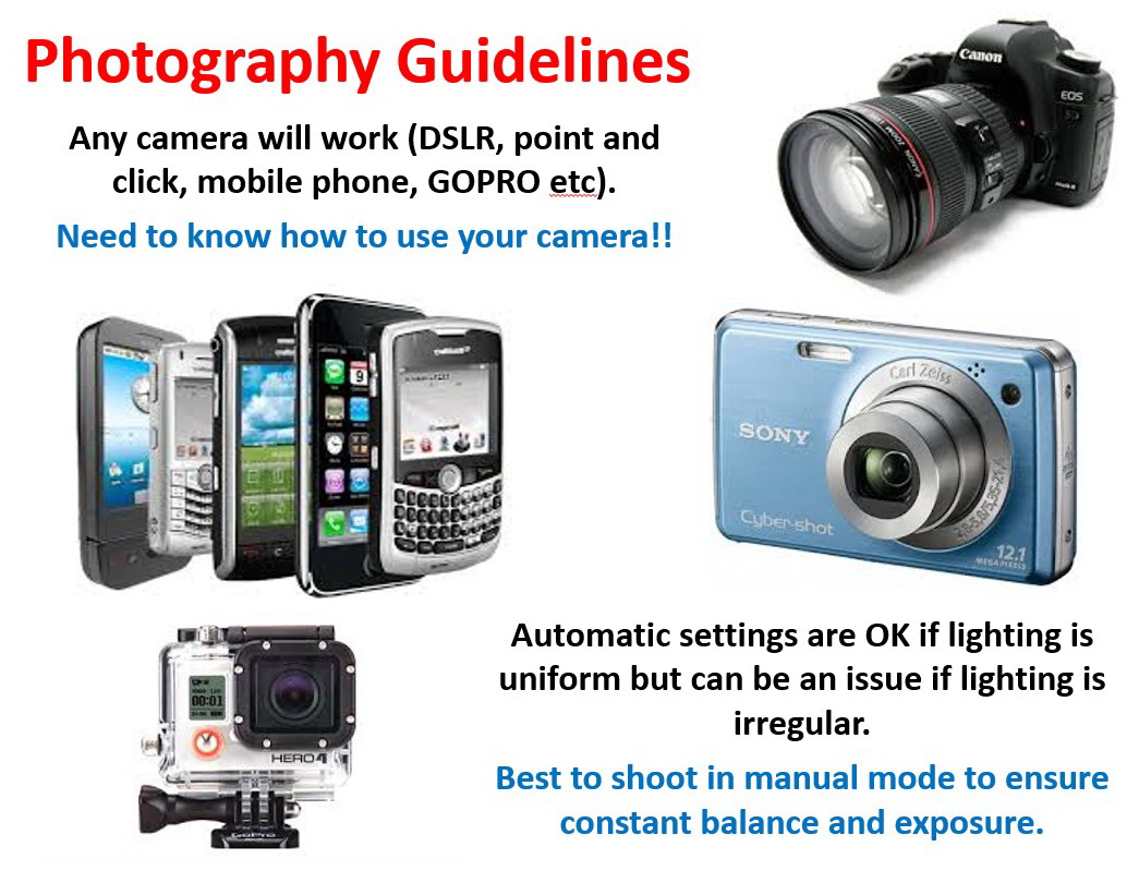
Image quality depends on the imaging device and on the skill and experience of the operator. Images collected in 'auto' mode often work well provided that the outcrop is reasonably large and uniformly lit. For small scale features, and in challenging lighting conditions, manual image control usually produces superior results. Good imaging in difficult conditions requires careful choice of factors such as exposure, white balance, exposure time, iso sensitivity and depth of field. Suggestions for image parameters are provided in a PDF (link to guidelines).
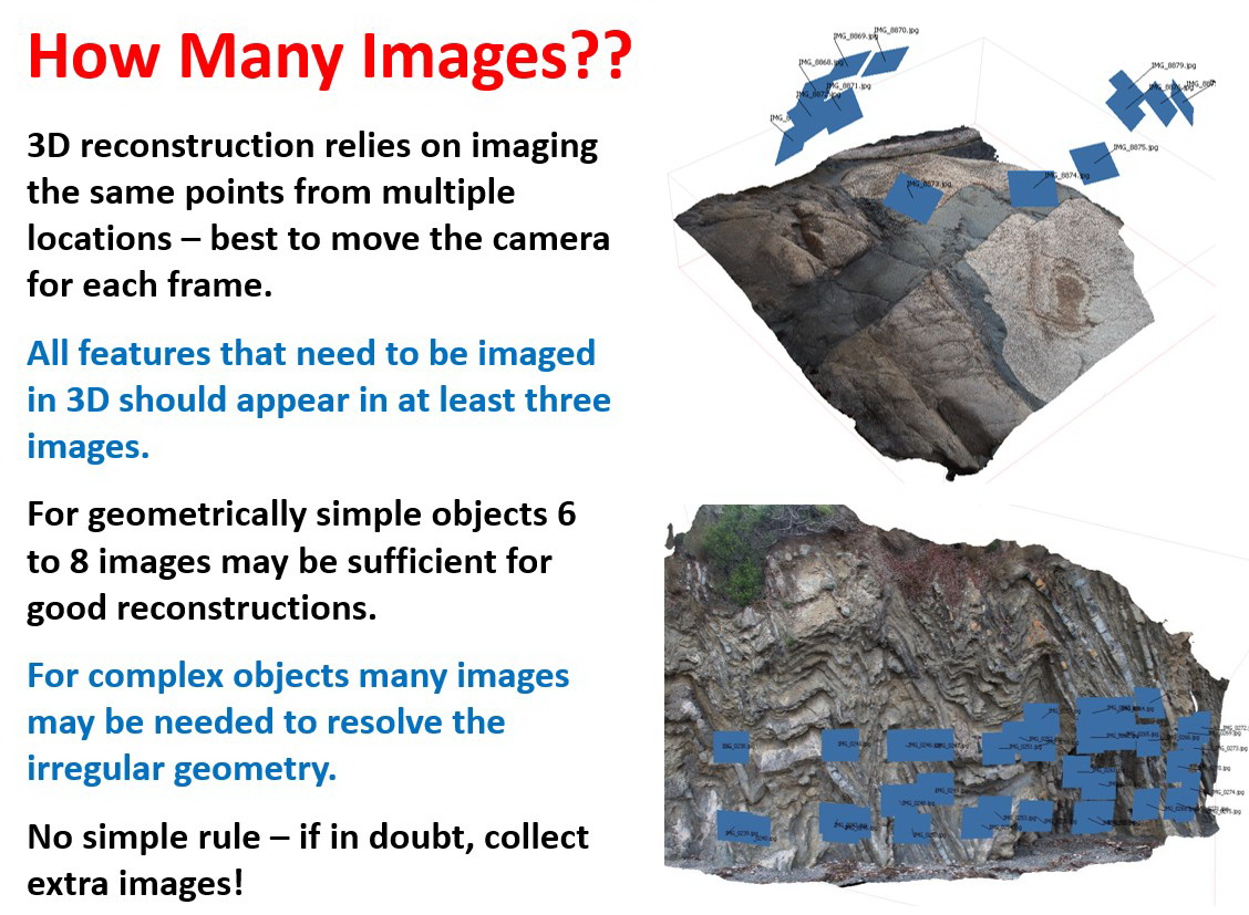
It is not possible to specify exactly how many images should be collected for a particular outcrop as this is determined primarily by the geometric complexity of the outcrop and the physical extent of the features being imaged. For small and medium scale outcrops that are not particularly geometrically complex, as little as 6-8 images may be required to obtain a good quality result. However, for large complex features 10s or 100s of images may be needed. For geometrically complex outcrops the relative positions and orientations of the images is very important. Every feature of an outcrop that is to be depicted in the final 3D model needs to be imaged in at least two and preferably more images.
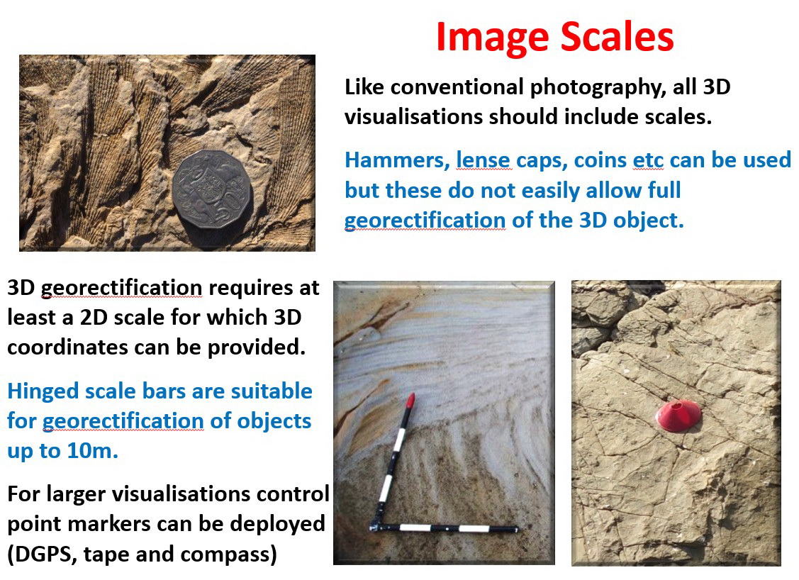
Scales are included in most AusGeol 3D images (except those where physical access to a site was not possible). Simple scale objects, such as a geological hammer, coin or pen, are OK for qualitative evaluation but do not allow full georectification of the final 3D model. A two dimensional scale bar with known orientation is required for rectification. For large and medium scale (>10m to ~1m objects) we use hinged scale bars that are painted with 10cm black and white bands. A 1m scale bar (10 x 10cm divisions) is commonly used for large objects and a 0.5m (5 x10cm divisions) bar for medium and small scale features. Where possible, these scale bars are positioned on, or adjacent to, the feature being imaged so that both arms of the scale are in an horizontal plane with the arm with the red end aligned towards UTM grid north and the other arm aligned to the east. In some cases it is not possible to position the scale in a horizontal plane and additional measurements are required in the field to specify the orientation of the scale for rectification of the model.
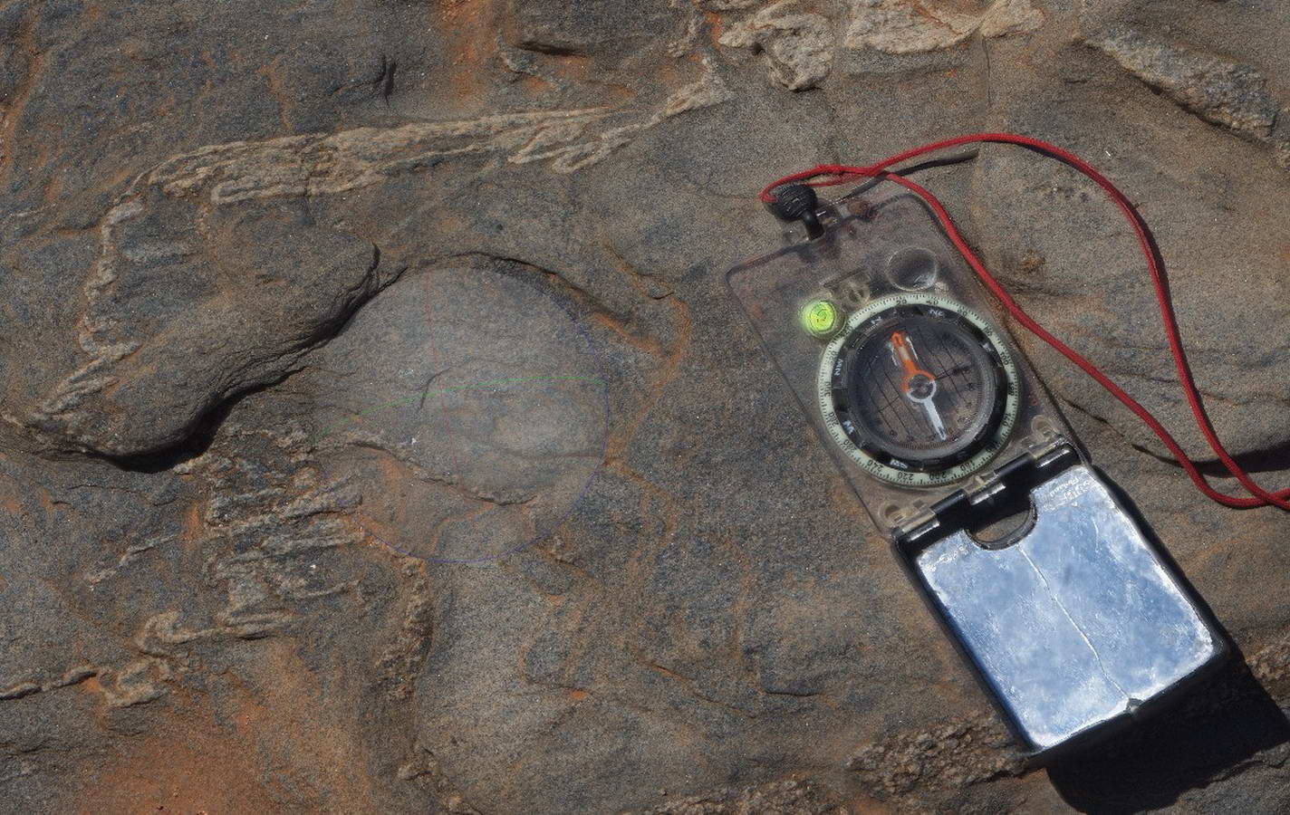
For small scale objects (~1m to ~0.3m) a geological compass is commonly used as a scale object. The base of the compass is aligned in an horizontal plane and the long edges of the compass are oriented in the UTM grid north-south orientation.
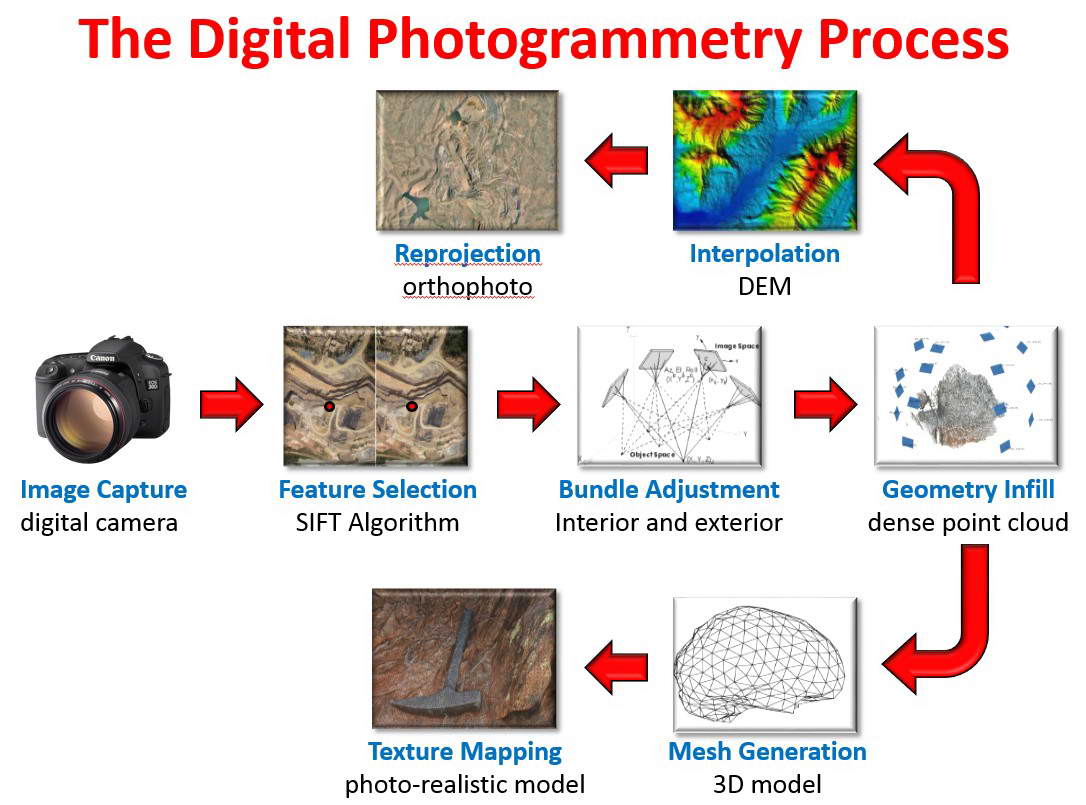
The digital photogrammetric process involves a number of stages. The first critical stage involves identification of features that are common to multiple images. This process employs a variant of the SIFT algorithm which identifies distinctive features (pixels) in each image, quantifies the local attributes of these features, and then correlates features between images based on the similarity of the attributes. Once many distinctive features (100s to1000s of features) have been identified and correlated between images the photogrammetry software then solves for the system unknowns which include the position and orientation of the image plane for each image (6 parameters) and the parameters that specify the optical characteristics of the camera lens (8 parameters). The process is an overdetermined problem and is solved by least squares optimisation. Once the system parameters are known, the features identified by the SIFT algorithm are positioned in 3D space to generate a sparse point cloud.
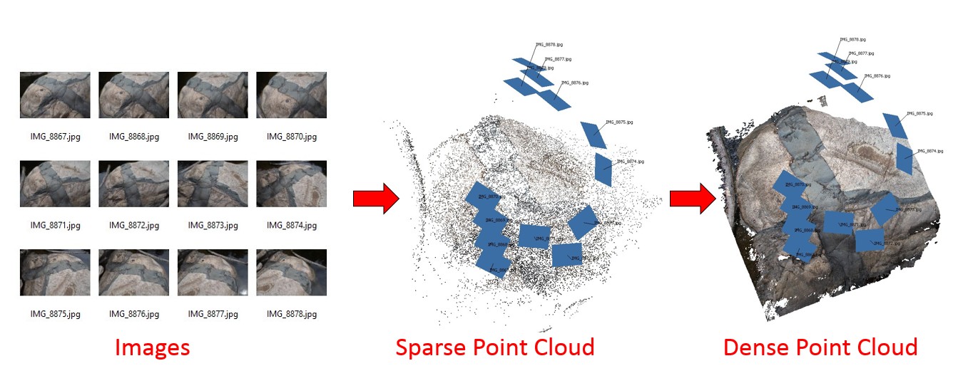
The next stage involves infill of the sparse point cloud to generate a dense point cloud which may have millions of points in 3D space. The algorithm utilised for this process is proprietry to AgiSoft and details of its operation are not provided. From the dense point cloud, a triangulated mesh is generated to represent the surface of the object.The number of triangle faces is determined by the operator based on the complexity of the outcrop and the likely application of the model. Models with large numbers of triangles are required when the geometry of the outcrop being imaged is complex while simple objects can be represented using less triangles. AusGeol 3D visualisations may contain between 10,000 and 250,000 triangles.
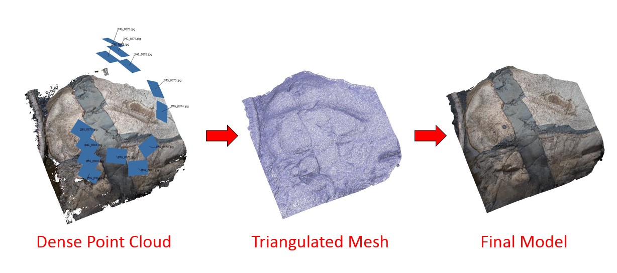
The final stage in the generation of a photo-realistic 3D geological model involves mapping the high resolution original imagery onto the triangulated model surface to to create a texture map. The detail and visual appearance of the model is determined by the size of the texture map. Most AusGeol full-resolution models use 8192 x 8192 pixel texture maps (the largest texture map supported in a 3D PDF). Additional photogrammetric model outputs such as digital elevation models and orthoimages can also be generated using Photoscan. Orthoimages are generated for many 3D models (see below).
UAV Models (VisType : UAV)
UAV models are a special class of 3D photogrammetric model for which photography has been acquired using a UAV.
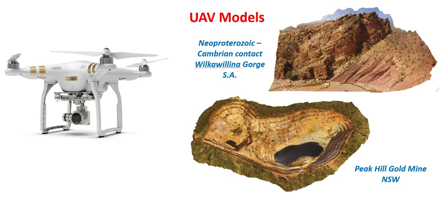
UAV photography provides views of large-scale geological features that cannot easily be imaged from purely terrestrial viewpoints. UAV data can be used to produce 3D texture-rendered models and also orthoimagery.
Pole Models (VisType : POLE)
UAV models are a special class of 3D photogrammetric model for which photography has been acquired using a pole.
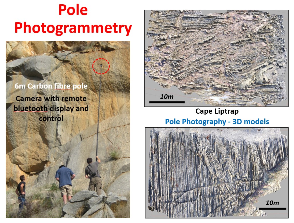
Pole photography provides views of medium-scale geological features that cannot easily be imaged from purely terrestrial viewpoints. Pole imagery can be used to produce 3D texture-rendered models and also orthoimagery.
Orthoimages (VisTypes : 3D, UAV, POLE)
Orthoimagery is provided for many AusGeol 3D models. Orthoimages are 2D images (in jpeg or ECW format) that provide detailed views of the 3D model from specific orientations. Orthoimages usually have a much higher spatial resolution than the corresponding 3D model. The visual representation of the model in 3D is controlled by a combination of the geometric complexity of the surface and the size of the texture map but is typically much lower than the resolution of the original photography. The resolution of an orthoimage can be close to the optical resolution of the original camera system. Orthoimages can be very large (100s Megapixels to Gigapixels) and provide 'deep-zoom' images that can display detailed features and also provide context at lower zoom levels.
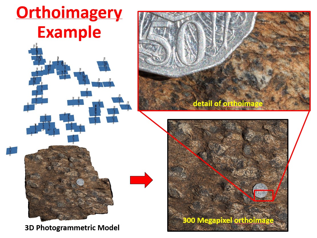
Orthoimages are particularly suitable for depicting detailed features on large flat outcrops. An orthoimage is not exactly equivalent to a single high resolution photograph of an outcrop taken from a fixed location since the intensity values for each pixel in the orthoimage are derived by projection parallel to the orthoimage view direction rather than radiating from a single viewpoint. An orthoimage is effectively an image acquired with the 'camera' positioned at infinity where raypaths are parallel.
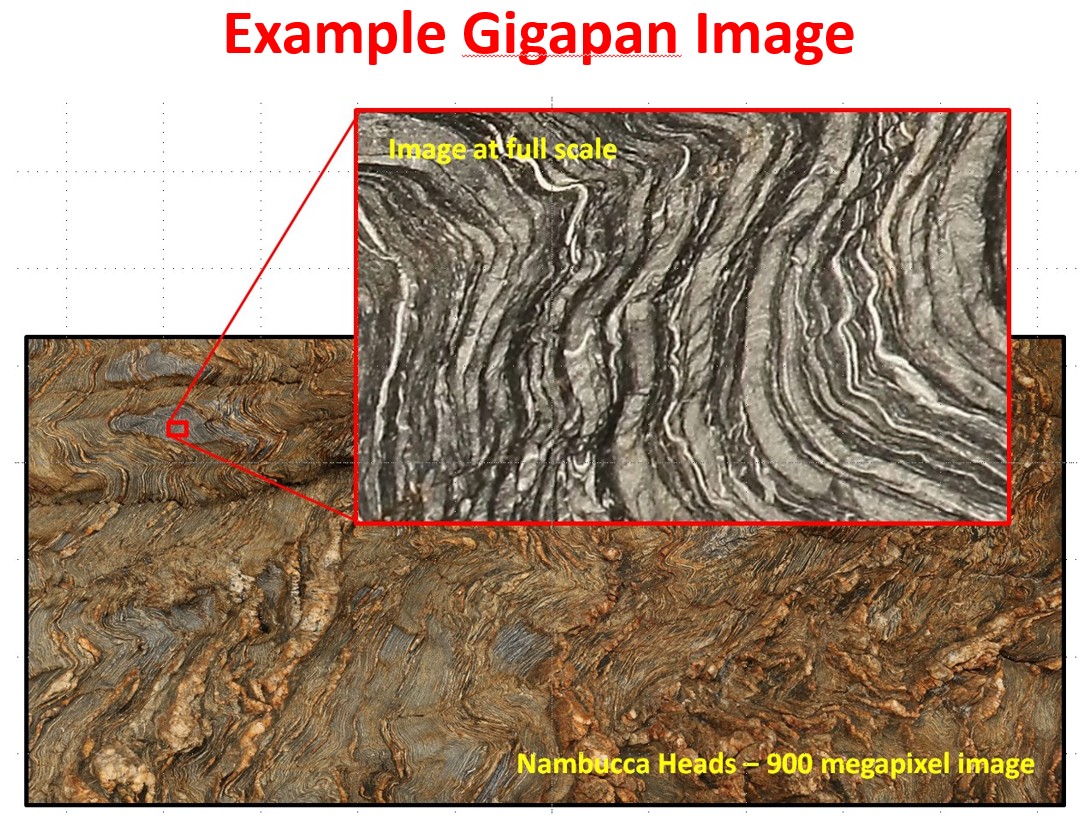
GigaPan Images (VisType : GIGA)
These 'deep zoom' images are acquired using a GigaPan robotic camera head that automates collection of 100s of images using a long focal length lens.
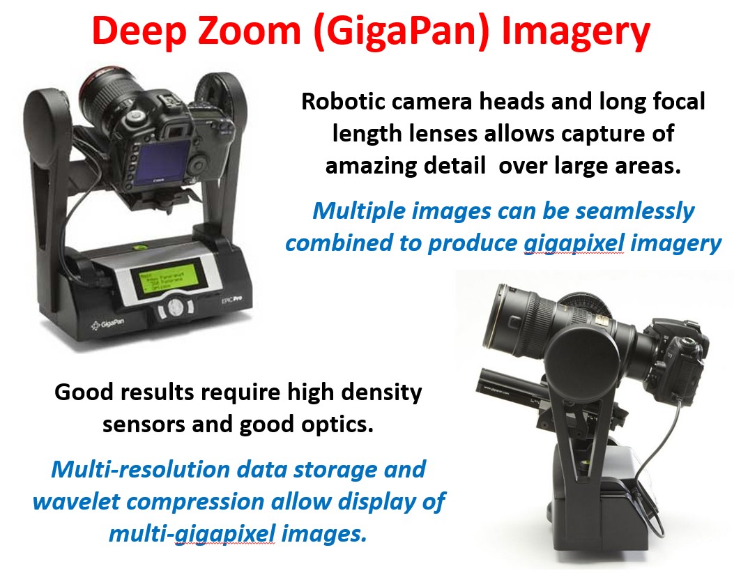
Images can be seamlessly stitched together to generate a single image with 100s of Megapixels to Gigapixels. GigaPan data collection is best suited to large to medium size outcrops where all features of interest are at approximately the same focal distance. GigaPan Imagery is delivered via the AusGeol website as a single file in ECW format.